Best Practice for Validating HCF Data Center Installations
Exceptional speed, resilience and low latency are critical for data center interconnect, with hollow core fiber (HCF) enabling significantly improved performance for these and other KPIs over traditional single-mode fiber (SMF). The technology’s trial and rollout is a priority deployment in sectors such as AI, quantum communications and cloud infrastructure.
But testing HCF using traditional approaches simply will not enable a true validation. Unlike SMF, HCF exhibits a weaker Rayleigh backscatter, with the backscatter being non-uniform. Adding to this is the high reflectivity from fiber transitions and splices, as well as its sensitivity to bending. Without taking these into consideration, false passes will be given, and significant problems created.
In this blog we’ll examine the role of test and measurement for successfully deploying HCF, with a guide on how to deploy and test links that include HCF.
How Does HCF Differ from Solid Core Fibers?
With traditional SMF, natural imperfections and impurities in the glass causes attenuation of an optical signal, which limits how far data can travel before needing amplification for highly demanding applications.
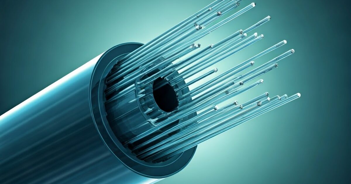
Unlike conventional SMF, which uses a solid glass core, HCF’s center channel is mostly empty. It’s a tube of glass containing nested glass capillary tubes that use an anti-resonant effect to confine the great majority of transmitted light within the hollow core, substantially reducing, though not fully eliminating, its interaction with the surrounding glass.
The result is that interactions between the transmitted light and the fiber material are greatly reduced, with substantial performance gains seen. This includes faster propagation and significantly reduced latency and signal distortion.
Light travels 4.9 µs/km in SMF and increases to 3.3 µs/km in HCF, which is close to its in-vacuum velocity, giving up to a 33% reduction in latency. This is coupled with a markedly lower chromatic dispersion (up to 70% for operating bands) and reduced attenuation (up to 65%), as well as improvements in nonlinear effects and an ability to handle higher optical powers without thermal damage.
As such, HCF is gaining traction in applications where speed, security and low latency are critical: financial trading, defense and secure communications, quantum cryptography and AI data centers
Deployment and Testing Challenges
HCF may offer transformative speed and performance, but its fabrication is vastly more complex, as is splicing. In addition, the fibers themselves can be more mechanically fragile than standard glass. Validation is particularly challenging, with tests for splice quality, connector losses and fiber integrity all requiring a different approach to SMF, with its design altering the optical signatures relied upon by traditional OTDR techniques. This is particularly true over long distances.
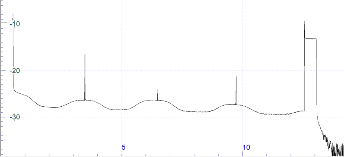
Four physical effects are particularly important to note. First, in HCF fibers, Rayleigh backscatter is much weaker (typically around 14 to 20 dB lower versus SMF), which reduces OTDR trace visibility and limits event detection and distance measurement with standard OTDR. Second, backscatter coefficient is not uniform and microstructural variations along the fiber length, coupled with the presence of different gases from the splicing processes, will complicate unidirectional OTDR trace interpretation. Third, fiber transitions and HCF-to-HCF splices introduce strong reflections, creating OTDR dead zones. Lastly, HCF’s increased sensitivity to bending versus standard glass can create attenuation spikes that are easily misinterpreted as poor splices or missed due to the fluctuating backscatter levels.
Complicating things further, when HCF is spliced in the field, ambient air can bleed into the open core and create localized gas absorption regions that further distort OTDR traces.
These effects make many familiar single‑ended or assumption‑based measurements unreliable if they are interpreted in the same way as for SMF. Test equipment and analysis methodologies all need to be carefully selected to prevent impairments being overlooked, or benign features being misclassified as defects.
OTDR Test and Analysis – and the Need for Bidirectional Testing
By combining OTDR analyses for measurements taken from opposite ends of the fiber, it’s possible to suppress backscatter‑related artefacts. This (AB−BA)/2 bidirectional calculation can be used to reveal the true Loss Profile of the link, but it should be noted that standard bidirectional analysis algorithms are not always sufficient for assessing splice loss, transition loss and distributed attenuation. A custom OTDR post-processing algorithm is necessary for reliable HCF characterization, qualification and certification.
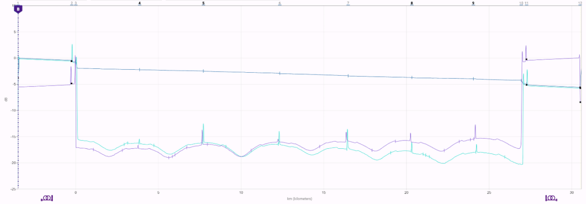
At the same time, the combination of low backscatter levels, variable backscatter coefficient and highly reflective fiber transitions (such as launch fiber to HCF under test) also places stringent demands on OTDR performance and configuration flexibility. An OTDR with a higher dynamic range at short pulse widths is therefore needed to measure each splice without any merging of events. Dynamic range at short pulse widths is far more important than headline dynamic range figures quoted at long pulses. In addition, without sufficient performance margin, dead zones and trace tailing can obscure critical events.
HCFs also tend to be optimized for operation in the S-band (starting around 1450 nm) and above. Testing at 1550 nm is therefore required and, as per SMF testing, the use of additional wavelengths will enable better fiber and splice loss characterization and bend detection, with testing at 1625 nm also recommended for field acceptance testing.
Additional Testing Requirements
Attention should also be paid to attenuation profile (AP), chromatic dispersion (CD) and polarization mode dispersion (PMD).
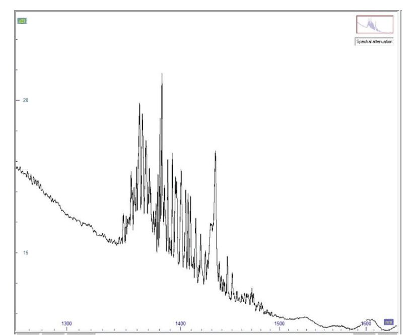
Attenuation profile testing helps identify non-ideal transmission characteristics, such as absorption regions caused by water vapor. While the AP of standard glass fibers is well known, and consistent from one manufacturer to another, the same cannot be said for HCF. Instead, the industry is in the early stages of production and deployment, with differing manufacturing processes leading to different profiles. It is vital to validate the actual transmission capacity of the link, confirm manufacturer specifications and ensure compatibility with system requirements. This is doubly so in applications where wavelength-specific performance is critical.
Despite HCF’s inherently low CD and modest PMD, testing these is also vital. HCF manufacturing processes continue to evolve, and installed links often contain multiple splices between fiber segments. Dispersion measurements therefore provide a baseline characterization that supports future transmission upgrades and helps rule out unexpected behaviour introduced during installation.
Test equipment implementation and performance are also important. Dispersion testing methods that rely on OTDR-derived measurements can be severely limited by the low backscatter levels. Dedicated optical source and receiver-based techniques are far better suited for medium to long HCF spans, as they are not constrained by OTDR dynamic range trade-offs in the same way.
Implementing an HCF Certification Strategy
To summarize, a credible HCF certification strategy combines:
- Bidirectional OTDR analysis to obtain true HCF loss profile
- Careful measurement of splice losses and bend effects
- Dispersion characterization to establish a reliable performance baseline
- Wide-band spectral attenuation measurements to validate transmission windows
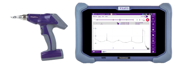
OTDR such as the VIAVI 8100 series D module are well suited to testing HCF, and offer a dynamic range at short pulse widths, with good dead zone performance, photodiode sensitivity and recovery capabilities. In addition, optical broadband light sources and receivers, such as VIAVI’s OBS-500 and the VIAVI Optical Dispersion Measurement (ODM) module can be used to overcome the issue of RBS drop for improved accuracy over longer distances. Both of these modules can be hosted on the OneAdvisor 800 Fiber platform, with the VIAVI Report PRO software enabling the Loss Profile report generation.
Additionally, automated inspection probe microscopes such as VIAVI’s INX 700 with AI-enhanced image analysis can be used to ensure end-face cleanliness at critical SMF-to-HCF transitions, keeping reflections below -50 dB and preventing dead zones from masking adjacent events.
More information on the above products as well as the unique challenges and requirements of HCF validation is available to download via a free application note.