Testing and Certifying Hollow Core Fiber: From Novel Physics to Network Ready Infrastructure

Hollow core fiber (HCF) is rapidly transitioning from lab research into field trials and early operational deployments. Its ability to guide light through a predominantly air‑filled core rather than solid glass enables tangible performance gains, most notably lower attenuation, reduced latency, and less signal distortion. These properties make HCF especially attractive, particularly for data center interconnect (DCI), high-speed metro and long-haul networks, and other latency sensitive network applications.
However, the same physical properties that enable these benefits introduce new complexities when it comes to testing and certification. Conventional fiber test methods and assumptions, developed for solid‑core single‑mode fiber (SMF), are inadequate when applied directly to HCF. Applying them without adaptation risks inaccurate measurements and misleading conclusions.
So why bother with HCF? What’s the benefit?
HCF offers clear and measurable advantages:
- Lower latency: Light travels faster in HCF, closer to its velocity in vacuum, resulting in a delay of approximately 3.33 µs/km, compared with roughly 4.9 µs/km in SMF.
- Reduced chromatic dispersion: Typical values are below 5 ps/nm/km, versus approximately 17 ps/nm/km for standard SMF.
- Minimal nonlinear effects: Reduced light–glass interaction leads to negligible nonlinear effects.
- Lower attenuation: in specific wavelength bands, advanced designs have demonstrated results below 0.1 dB/km.
Individually, each of these benefits is attractive, but together they enable and drive specific applications for DCI and AI workloads and next-generation optical transport.
Why Hollow Core Fiber Demands a Different Testing Approach
HCF’s air‑guided design reduces interaction between light and glass. At the same time, this design alters the optical signatures relied upon by traditional OTDR test techniques.
Three physical effects are particularly important to note:
- Rayleigh backscatter is much weaker, typically around 14–20 dB lower than in SMF, reducing OTDR trace visibility and limiting event detection and distance measurement with standard OTDR settings.
- Backscatter coefficient is not uniform; microstructural variations along the fiber length and presence of different gases from the splicing processes cause backscatter levels to vary, complicating uni-directional OTDR trace interpretation and necessitating bidirectional OTDR analysis.
- Highly reflective transitions and splices, transitions from SMF to HCF, and even HCF to HCF splicing can introduce strong reflections creating OTDR dead zones.
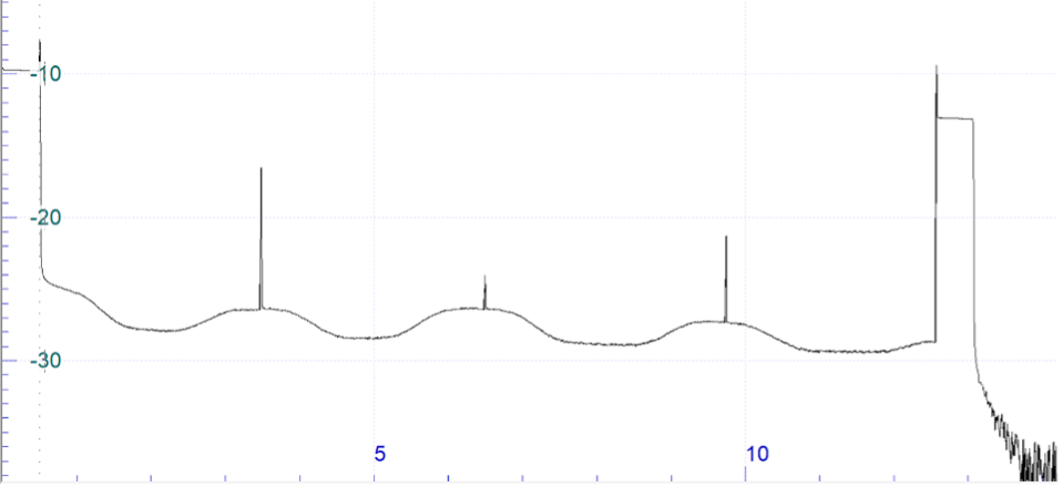
Regular uni-directional OTDR trace showing the transitions from SMF to HCF, variation of RBS coefficient in the trace and reflective splices
These effects make many familiar single‑ended or assumption‑based measurements unreliable if they are interpreted in the same way as regular SMF results. Without selecting the right type of test equipment and adapting test methodologies, operators risk either overlooking real impairments or misclassifying benign features as defects.
Rethinking Certification for Hollow Core Fiber
For established fiber types, certification is often reduced to a small set of acceptance metrics. For HCF, a credible approach must focus on characterization rather than simple pass/fail validation.
A meaningful certification outcome should demonstrate:
- True end‑to‑end attenuation
- Accurate identification and quantification of splices and fiber transitions
- Dispersion characteristics aligned with the intended transmission application
- Stable performance across the relevant wavelength range
This broader view reflects the current reality: hollow‑core designs are still evolving, and deployments represent significant capital investment. Certification must therefore provide assurance not just for day‑one activation, but for long‑term operational viability.
The Role of Bidirectional OTDR Test and Analysis
One of the most important differences between HCF and conventional fiber lies in how attenuation is measured.
Because backscatter levels in HCF are both weaker and less uniform, single‑ended OTDR measurements can distort apparent loss. Changes in backscatter levels may appear as loss events even when no additional attenuation is present. Bidirectional OTDR analysis overcomes this limitation by combining measurements taken from opposite ends of the fiber. By aligning the traces and applying a bidirectional calculation—commonly expressed as (AB − BA) / 2—backscatter‑related artefacts are suppressed, revealing the true “loss profile” of the link.
However, standard OTDR post-processing algorithms are often insufficient for the task. Custom software or expert manual interpretation is often needed to assess splice loss, transition loss, and distributed attenuation.
For hollow core fiber certification, this is not an enhancement. It’s a necessity.
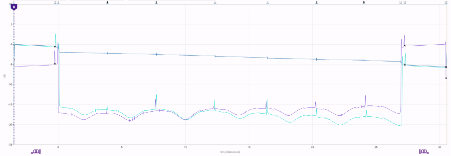
Loss profile trace obtained by performing bidirectional OTDR analysis
Can Any Old OTDR Be Used?
In short, no.
The combination of low backscatter levels, variable backscatter coefficient, and highly reflective transitions places stringent demands on OTDR performance and configuration flexibility.
The high SMF to HCF transition requires an OTDR with higher dynamic range performance. Splices could be 2 to 4 km apart; therefore, it is important to have an OTDR with high dynamic range at short pulse width to be able to measure each splice without merging of events. Usable dynamic range at short pulse widths becomes far more important than headline dynamic range figures quoted at long pulses. Without sufficient performance margin, dead zones and trace tailing can obscure critical events.
To learn about how to correctly spec an OTDR for HCF test and how to perform the bidirectional testing, results processing and analysis, take a look at our Testing Hollow Core Fiber (HCF) application note.
Wavelength Considerations and Spectral Behavior
Many hollow core designs are optimized for longer wavelengths, often beginning in the S-band starting around 1450 nm.
As a result:
- Measurements at 1310 nm may have limited diagnostic value
- Testing at 1550 nm and above is more representative of operational performance
- Additional long wavelength measurements improve sensitivity to bending and spectral loss anomalies.
Certification strategies should therefore align test wavelengths with the fiber’s intended transmission bands rather than relying on legacy defaults.
Beyond discrete wavelengths, overall spectral attenuation behavior is also important. Differences in fiber design, manufacturing processes, and gas infiltration can lead to potential absorption features outside the primary transmission band. For that reason, attenuation profile measurements across a wide wavelength range are increasingly regarded as a key part of HCF certification.
These measurements:
- Confirm that target transmission bands meet loss expectations
- Reveal absorption features caused by residual water vapor or presence of gas infiltration during the splicing process
- Expose non-uniform spectral behavior that could limit future wavelength plans
This spectral insight is especially relevant in data center and transport environments, where flexibility and upgrade headroom are strategic requirements.
Dispersion Still Matters Even When it’s “Low”
It is tempting to assume that HCF’s inherently low chromatic dispersion (CD) and modest polarization mode dispersion (PMD) eliminates the need for dispersion testing. In practice, the opposite is true.
HCF manufacturing processes continue to evolve, and installed links often contain multiple splices between fiber segments. Dispersion measurements provide a baseline characterization that supports future transmission upgrades and helps rule out unexpected behavior introduced during installation.
Again, test equipment implementation and performance are important. Dispersion testing methods that rely on OTDR-derived measurements can be severely limited by the low backscatter levels. Dedicated optical source and receiver-based techniques are therefore far better suited to long HCF spans, as they are not constrained by OTDR dynamic range trade-offs in the same way.
Dispersion characterization provides a quantitative baseline that supports:
- Validation of transmission design assumptions
- Comparison between fiber segments from different production runs
- Assessment of cumulative splicing effects
- Planning for higher symbol rates or longer reach in future upgrades
In the context of HCF, dispersion testing is less about troubleshooting and more about deployment confidence, ensuring that controlled laboratory performance translates into predictable field behavior.
From Emerging Technology to Operational Confidence
Hollow core fiber has the potential to redefine performance limits in optical networks. Its successful adoption, however, depends on testing and certification practices that acknowledge its unique physical behavior.
A credible HCF certification strategy combines:
- Bidirectional loss analysis to obtain true HCF loss profile
- Careful interpretation of transition, splice, and bend effects
- Dispersion characterization to establish a reliable performance baseline
- Wide-band spectral attenuation measurements to validate transmission windows
For network owners, testing and certification protects a high-value infrastructure investment. For system designers, it provides the confidence needed to deploy HCF at scale, knowing that what was designed can be delivered. In that sense, testing is not merely a deployment task for hollow‑core fiber; it is the enabling discipline that moves this new class of optical infrastructure from promise to production.
To learn more, take a look at our ‘What is Hollow Core Fiber (HCF) Testing?’ resource page.

