5G Beamforming Profile Rx

The prescription for precise SSB configuration
As 5G moves from the lab into the field, service provider (SP) deployment teams are learning about the nuances of different 5G NR implementations. Unsurprisingly, all 5G NR implementations are not the same, but getting a solid dose of understanding on beamforming and the impact of profile configuration is reliable advice for healthy 5G network performance.
Network equipment manufacturers (NEMs) deliver 5G NR equipment per standards, but as usual, standards do allow certain flexibility in achieving the final 5G NR performance targets. This can be a challenge for SP field and lab engineers as they work to establish a baseline across the performance among the brands of equipment that comprise their 5G NR infrastructure. From a basic radio conformance to complicated beamforming features, these factors need to be understood and analyzed so that SPs can scale up their deployments. Additionally, validating the existing RF environment, meaning spectrum clearance, and identifying any interference issues are essential for executing on a robust 5G deployment plan.
From a 5G radio perspective, the following must be understood during the field trial stage before a SP can confidently scale up to mass deployment:
- MIMO configuration
- Radio bandwidth
- Subcarrier spacing
- Sub 6GHz vs. mmWave spectrum
Knowledge of these elements forms the basis for an understanding of what needs to be tested and what tools and test solutions will be ideal to validate next generation Node B (AKA gNB) performance in the field. For example, a typical swept spectrum analyzer may not be the right solution for validating RF performance in a Time Division Duplex (TDD) network implementation. I will explore this topic in a future blog; here my focus is on the importance of understanding and analyzing beamforming and revealing the impact of variable profile configuration.
Beamforming Defined: Beamforming is the ability to generate and shape multiple beams using a much larger antenna array by manipulating the phase and amplitude of the arrays, thereby directing energy to a user’s specific service area. At higher frequencies, millimeter wave (small wavelength) makes it easy to integrate a larger array into a relatively smaller form factor.
Before we understand the intricacies of beamforming, it is essential spend some time studying synchronization signaling block (SSB). SSB carries primary sync signal (PSS), secondary sync signal (SSS) and the physical broadcast channel (PBCH).
So why SSB is relevant? SSB is used by the UEs or CPEs (phones, modems, etc.) for network acquisition. Basically, the SSB transmits the different reference signals that allow user devices to attach to the networks. Hence, when installing and commissioning a new 5G cell site, one of the first steps to take is to validate the SSB is transmitting correctly. If that is not the case, then devices will not be able to connect to the network.
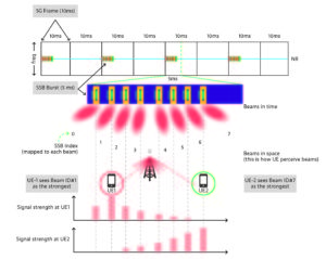
At any point in time, multiple SSBs are transmitted as shown below. The possible number of reference beams transmitted in 5G NR depends on the frequency range (FR) of operation. In FR2 the 3GPP standards allow for up to 64 beams; however, for lower frequencies in FR1, these can be either 4 or 8 beams.
To review, SSB includes the reference signals that conform the reference beams (sometimes referred to as coverage beams) and these beams are used for network acquisition by the user devices.
Let’s walk through an example of network acquisition.
First, the cell site transmits the synchronization block in bursts of 5 milliseconds within a 10-millisecond frame. This produces the actual broadcasting of the reference beams. In this example, up to 8 beams will be transmitted. These reference beams are available now over the air to any UEs inside the coverage area. Keep in mind that every beam is radiating at a different angle and therefore each phone may “see” predominantly the beam that is stronger depending upon the actual angle of arrival.
And in this simple example we show how UE 1 would identify and attach to the network through beam number #1 where UE-2 does the same but though beam number #7.
The challenge many SPs now face is that 3GPP standards are rather flexible when it comes to defining the actual location of the SSB block, particularly for FR2 carriers. Service providers don’t have any visibility into the way different NEMs configure their beamforming policies for 1x/2x/4x/8x or 64x beam distributions using phase shifting. Remember, if the SSBs are not configured correctly, the UE attach procedure will fail.
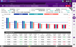
What can help in a situation such as this is a persistent real time spectrum analyzer (RTSA) for testing 5GNR signals. A 5G NR signal analyzer with RTSA function quickly can identify the presence and location of the SSB within the 5G carrier. With the help of a directional (horn) antenna and 5GNR-capable RTSA, the SP engineers can effectively identify each individual beam transmission from every downlink angle.

Service Providers worldwide rely on the VIAVI CellAdvisor 5G to test beamforming profiles and MIMO performance to ensure that their 5G networks deliver a reliable end-user experience. Visit VIAVI at Mobile World Congress LA, booth 2352, to see the difference an RTSA can make for your customers and go to the VIAVI 5G Deployment hub to check out more 5G testing resources including those listed below:
Case Study: Using CellAdvisor for Beam Analysis
RCR Wireless Editorial Report: 5G Beamforming Technology: Key to new network and device experiences


